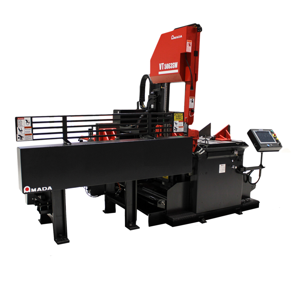
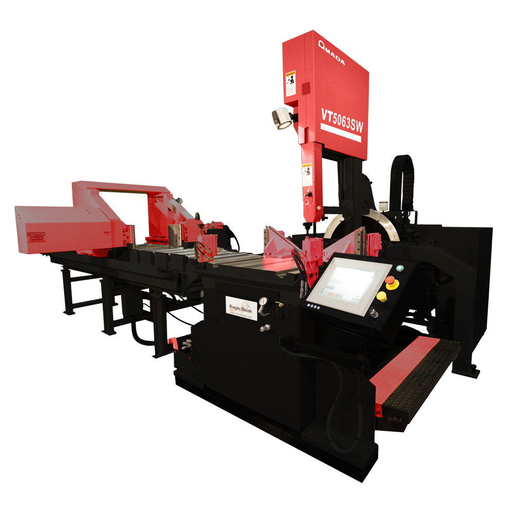
| Model | VT5063SW | |||
|---|---|---|---|---|
|
Cutting Capacity |
Round (Diameter) |
at 0° | 20.0″ | 508 mm |
| at 45° | 17.0″ | 432 mm | ||
| at 60° | 11.25″ | 286 mm | ||
| Rectangle (W x H) |
at 0° | 20.0″ x 25.0″ | 508 x 635 mm | |
| at 45° | 20.0″ x 17.0″ | 508 x 432 mm | ||
| at 60° | 20.0″ x 11.25″ | 508 x 286 mm | ||
| Maximum Vise Opening |
20.25″ | 514 mm | ||
| Work Load Capacity | 8,000 lbs | 3,628 kg | ||
| Saw Blade |
Dimensions (L x T x W) | 18′ 2″ x 0.050″ x 1-1/2″ | 5537 x 1.3 x 41 mm | |
| Blade Speed | 30-500 ft./min by Inverter | 9-152 m/min by Inverter | ||
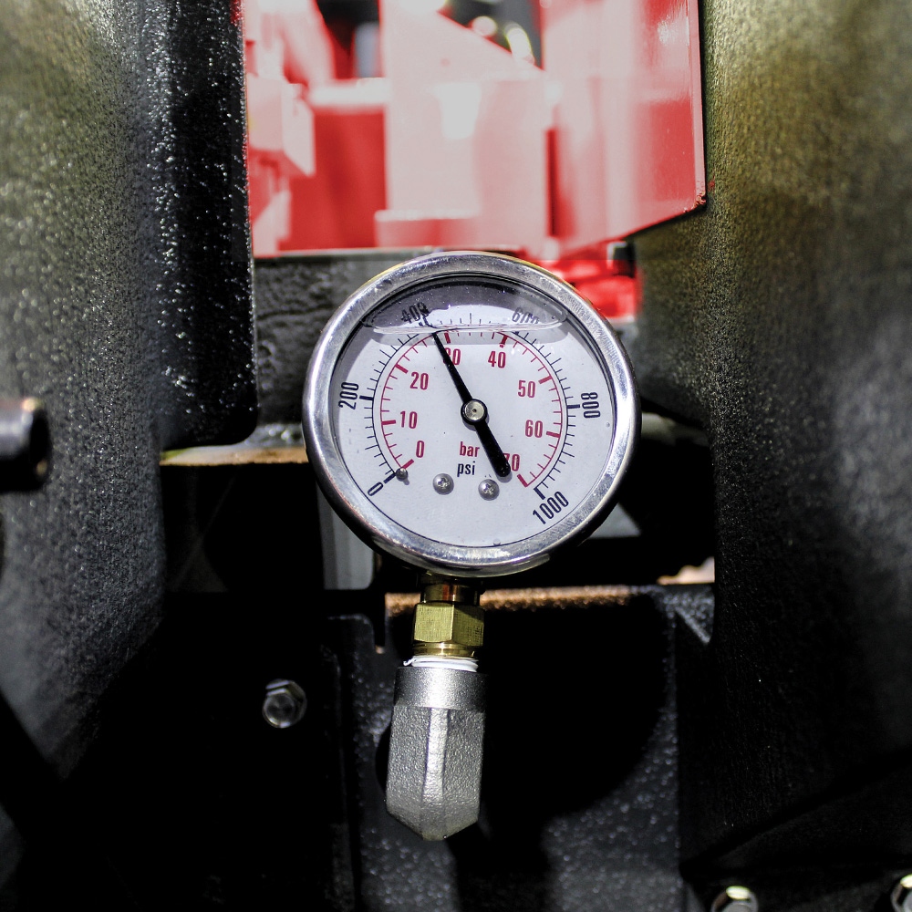
| Tension Control | Hydraulic | |||
| Blade Control |
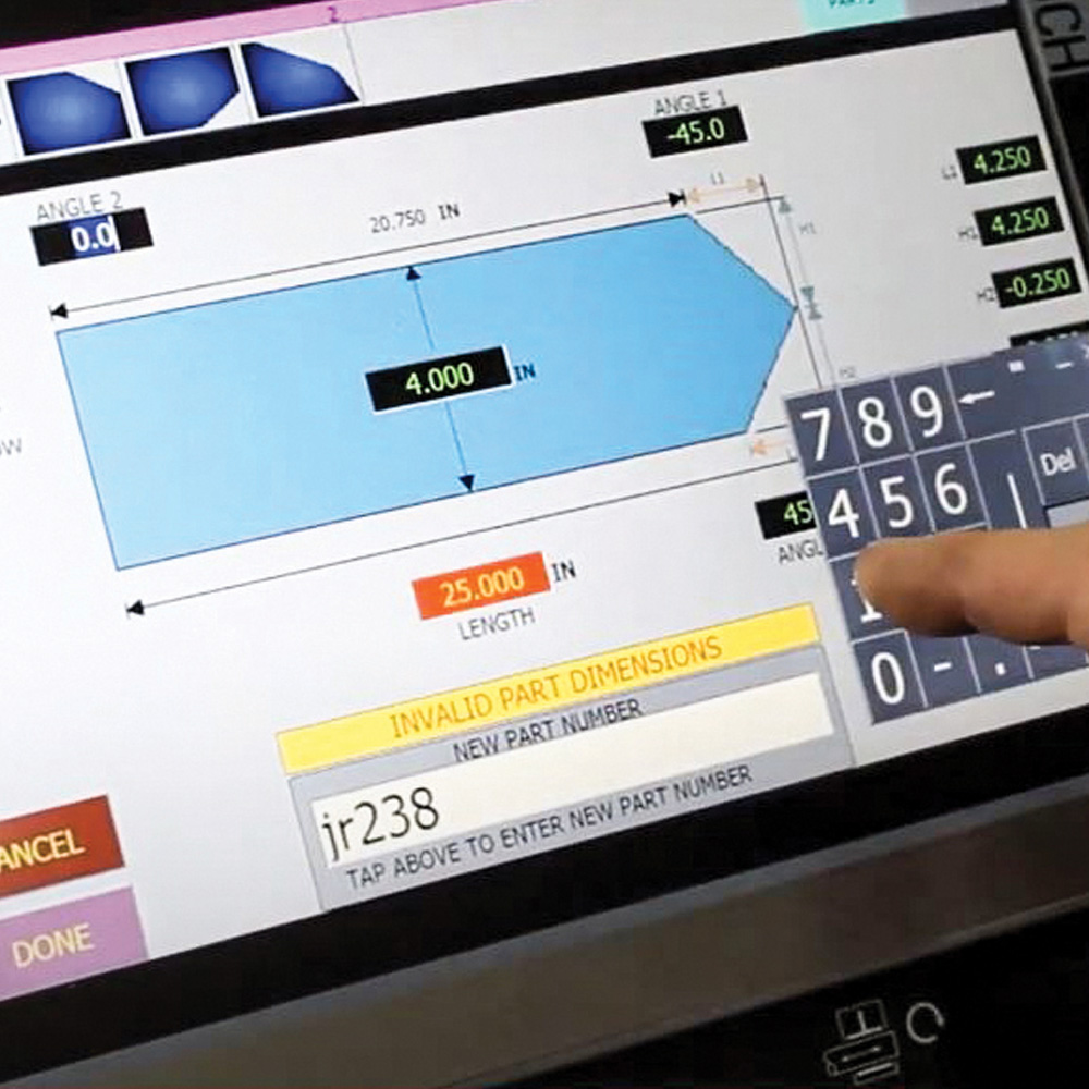
Cutting Control | Direct Force Sensing Electric Ball Screw with PC3 Programmable Control |
||
| Blade Feed Force | 0 to 300 lbs | 0 to 1334 N | ||
| Vise Operation |
Type | Main Vise (Optional second vise is available to install) |
||
| Control | Hydraulic, Full Stroking with 9-12″ High x 15″ Wide 60° Faceplates |
|||
| Motors |
Saw Blade | 10 HP |
7.4 kW | |
| Hydraulic Pump | 5 HP | 3.7 kW | ||
| Cutting Fluid Pump | 1/8 HP | 0.1 kW | ||
| Tilt Gear | 1/15 HP | 0.05 kW | ||
| Power Requirement |
Power Supply Voltage | AC230V±10% or AC460V±10%, 3 PH, 60 Hz Voltage must be specified when ordering |
||
| Power Requirement | ||||
| Cutting Fluid |
Tank Capacity | 60 gal | 227 liters | |
| Pump Type | Electric | |||
| Hydraulic |
Tank Capacity | 10 gal | 38 liters | |
| Chip Disposal |
Manual |
|||
| Standard Feed Vise |
Index Mechanism | Shuttle Vise | ||
| Material Index | AC Servo Motor and Ball Screw | |||
| Feed Stroke | 48″ | 1219 mm | ||
| Remnant Length | 23″ Plus Length of Parts | 584 mm Plus Length of Parts | ||
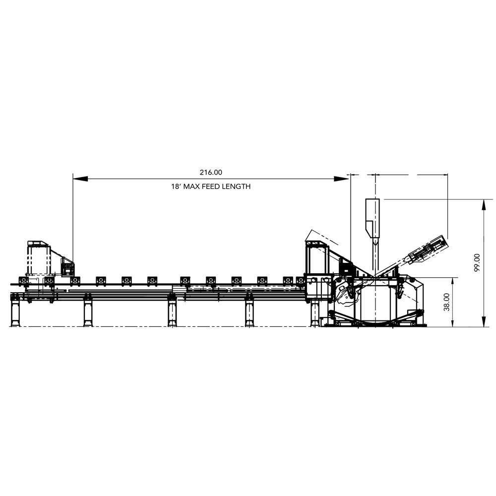
| Optional Shuttle Table |
Feed Mechanism | Automatic Servo Drive Index with Linear Guide System | ||
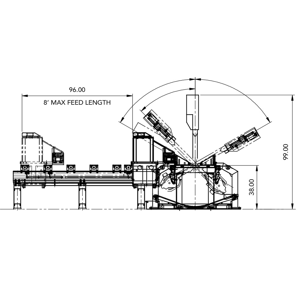
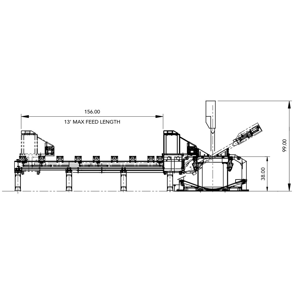
| Feed Stroke | 8, 13 and 18ft (It must be specified when ordering) |
2438, 3962 and 5486mm (It must be specified when ordering) |
||
| Machine Dimensions (W x L x H) | 94.7″ x 99.2″ x 90.8″ | 2404 x 2518 x 2305 mm | ||
| Table Height (Above Floor) | 40.0″ | 1016 mm | ||
| Machine Weight | 8,300 lbs | 3,727 kg | ||
Specifications and the machine design may change without notice at the sole discretion of Amada’s Engineering Department.
Contact for repair and recovery of AMADA products and our corporate activities.